
The Inspiration
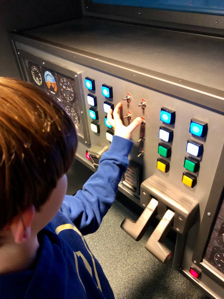
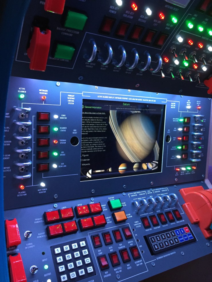
This project started from the idea of the airplane cockpit exhibit we loved when we visited the Children’s Museum of New Hampshire. Tristan showed immediate interest in the cockpit set up and frequently returned to the exhibit to explore it. One of the best ways you can see what your child gravitates to sensory wise is through museums and then see if you can make it yourself!

After our trip, I naturally went to Pinterest and Instructables to look for additional inspiration. I found several people who had made really cool setups for their kids including their own space station desks! I really wanted something that was portable and not tied to the wall however since he spends so much of his time in the main living area (near the sensory gym). There’s nothing on the market like this so finding things was sparse. When mentioning this to my now fiancée, he said that’s pretty easy to do as a rechargeable unit. I was blown away. That made my plans come to realization as I didn’t want to keep opening the box to put batteries for instance but just have an adapter plug-in instead.


Benefits of an Electrical Sensory Box
One of Tristan’s main strengths as an individual on the spectrum is that he is cause and effect learner. I even got it written into the IEP as a learning strategy! This electrical box exactly replicates cause and effect in very concrete ways that Tristan can operate. It also helps with fine motor skills of working the switches and the rotary switch allows him to work on turning his wrist. It is also just plain fun!
What You Will Need
- Box Parts: (Estimated $175)
- Buttons: (Estimated $195)
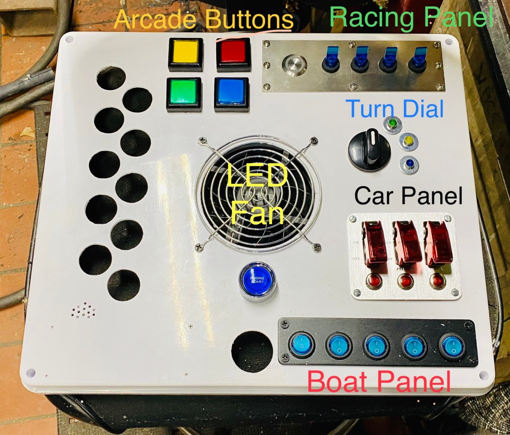
- Engine Start Button for Car Racing
- Duckbill Toggle Switch Panel from a Car Racing Panel
- Momentary Push Buttons from Arcade Machines
- LED Computer Fan
- Protected Toggle Switch Panel from a Car Racing Panel
- Rotary Switch
- Indicator Lights (plus some washers to go behind them for a more finished look)
- Rocker Switch Panel for Boats
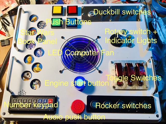
- Audio Push Button from a Space Book
- Star Wars Audio Panel from a Star Wars Book
- Number Keypad from Jameco Electronics
- Tools:
- Soldering Iron
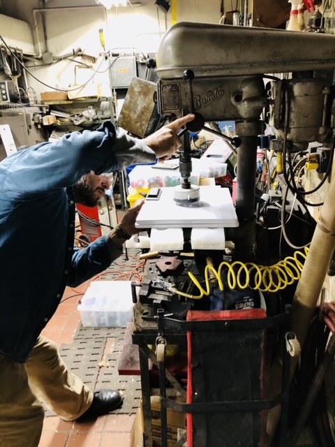
- Hole Saws
- Hand Drill or Drill Press
- Slug Buster
- Total Estimated Price: $370 (definitely my most expensive DIY so far)
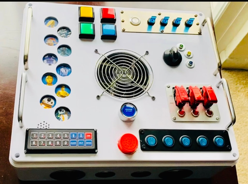
The Design
Initially in my layout I was thinking it would be cool to have some acrylic tubes filled with various things that could float and put them over the fan. I am still working on this part of the project! LOL


Part 1: Computer LED Fan
Since the highlight of the electrical sensory box is the computer LED fan, we wanted to work on that first to make sure there was enough space for it. You may choose not to have one in your design of course. We used a hole saw to cut a 4″ circle for the fan opening and attached the fan.
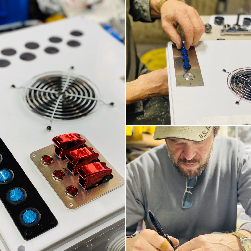
If you layout your switches, be sure you have clearance since there are nuts on the backs of the buttons. This way you don’t overlap spaces and it keeps the wires away from fan opening. Make sure the grill you choose allows for enough air flow to the box. A mistake we first made using a fine mesh grill instead of a more standard computer fan grill.
Part 2: Buttons and Switches
We began marking the areas for the book punchouts (could also make a stencil if easier). We drilled little holes for where the speaker is on the underside of the book panel so the sound could come out of the box.
We then marked and cut out holes for the duckbill switches panel and put the switches in from inside the box. Be sure you don’t choose momentary unless you want them to only have the light working while it is pressed. Lesson learned! So instead, each of the duckbill toggles control the indicating lights of the momentary switches since I already bought them.
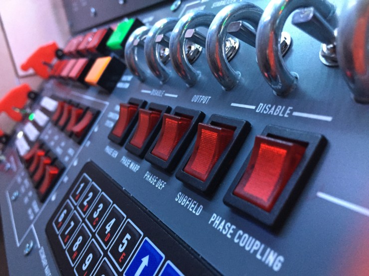
Next was the boat panel with the rocker switches. This was awful – I would not recommend purchasing boat panels in the future since each light had to be disconnected then reconnected on the opposite side of the box. A long and tedious process.
Next was the car ignition panel (protected toggle switches with indicator lights) – one big rectangle cut out plus holes for indicator lights.
** Be careful doing too many buttons as I was told that it might take away from the integrity of the box and supports that it needed (as it was made out of plastic).
Rotary switch – be careful purchasing this as some of them are stacked contactors (the box may not have enough depth to hold them). So the rotary controls a few small indicator lights. We put a washer behind them to make them look more fancy. It also added a little more strength and support from being pushed in by Tristan.
The number pad was added mainly for sensory input and it has a seriously satisfying click to it!
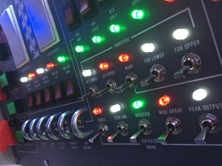
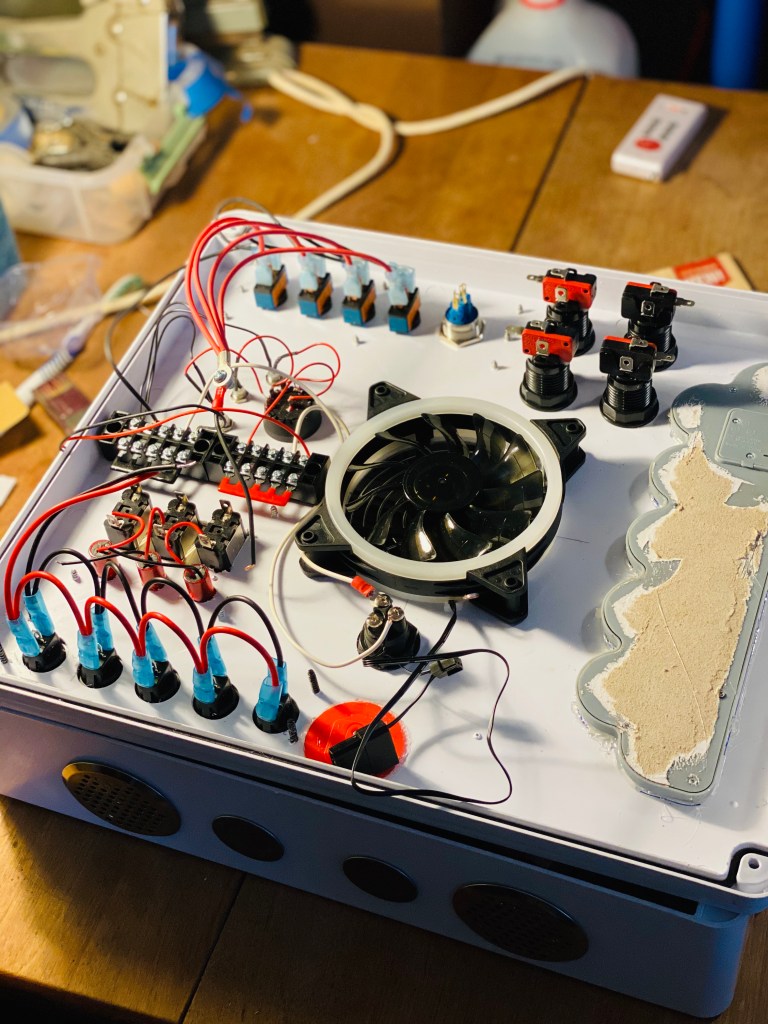
Part 3: Wiring the Switches
We planned ahead and used terminal blocks so the power could run to a central location. The battery pack would have a positive and negative terminal block to match. Each switch light combination has to have a positive and a negative to work. So the DC power can flow and complete each circuit.
Stick with red for positive and black for negative for wiring (for the most part). A lot of the switches already came with that color combination.
Each switch that has an indicator light also has an output to go to something in the real world, but for this project we just decided that the toggles only operate the lights.
So the fan is on a relay with a timer so we are not killing the battery. (Tristan would definitely do this). That way it shuts off by itself after 15 minutes. The engine start button also has an indicator light button put in and the stop button opens the circuit for the relay. So you can stop it before 15 minutes. Each of those switches is just a momentary switch. When you press the engine start, the power goes through the timer and activates the relay which puts the power to the fan (and its’ light). You can open the circuit before the elapsed time by pushing the stop button or just when the time elapses, you have to hit the stop button to reactivate the start circuit again. Tristan picked up on that quickly. Each of those items, the relay and timer have a wiring diagram that can help you understand this as well. In electrical jargon it’s called a 3 wire electrical control circuit.
Power Supply: the rechargeable battery pack – made to have USB output (5v) but we used the charging port for input and output because it takes 12v to supply the box. He used the cord the came with it, the DC jack port (outside the box), transformer box supplies the jack port (outside), so one wire powers the box (the terminal block) and the other wire goes to the jack port to be then plugged into the wall for recharging. It can go about 3 days without needed to be charged depending on how much Tristan uses it. I tend to charge it every other night, however (just in case).
Then Karl soldered each connections — yikes!
Part 4: Additional Improvements
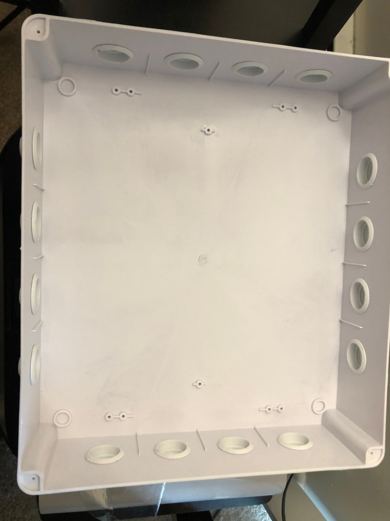
We put 8 snap in hole plugs (about 1 inch in size) over the punch-outs the electrical box already came with. The reason we did this is because the rubber caps that came with the box could easily come out and expose all the wiring to a very curious Tristan. Then we expanded the holes for 8 of the pre-cut punch-outs in the box on the sides and put 8 air vent holes to increase the air flow for the fan.
Karl suggested adding handles that stuck out enough over the switches to protect them since this was intended to be portable but also to protect the switches themselves. So if the box ended up on its face, the switches would not be impacted.
Finally I wanted to add some acrylic tubes as an attachment for the future. These would be filled with items that could easily float with the power of a DC voltage fan (small styrofoam balls, some types of confetti, and maybe even a ping pong ball). Hoping to work on these as a future project!