
The Inspiration
This DIY interactive LED color and sound display panel was inspired by looking through various special needs equipment magazines and websites. Not only do the colors light up to sound but can also be operated independently of sound. I dreamed of something like this for Tristan but not wanting to pay the inflated “special needs” price of the item. While inspirational and beautiful, many of these companies list the price as something that is unattainable for families with a special needs member (since we are already paying 3x what a “typical” child usually costs a family). The ticket price on the items below in the gallery range from: $2000 – $3500. Some of this is not the companies’ fault but rather the original producers of the item. The range for my DIY take on this can be anywhere from $200 – $450.
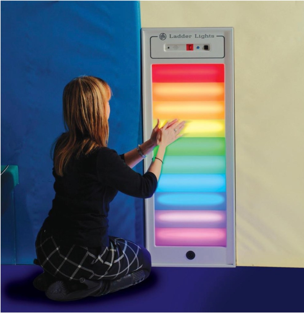
TFH Ladder Lights $2000 
eSpecial Needs’ LED Light to Sound Panel $2500 
eSpecial Needs’ Interactive LED Fanlite $2750 
eSpecial Needs’ Interactive Ladderlite $2650 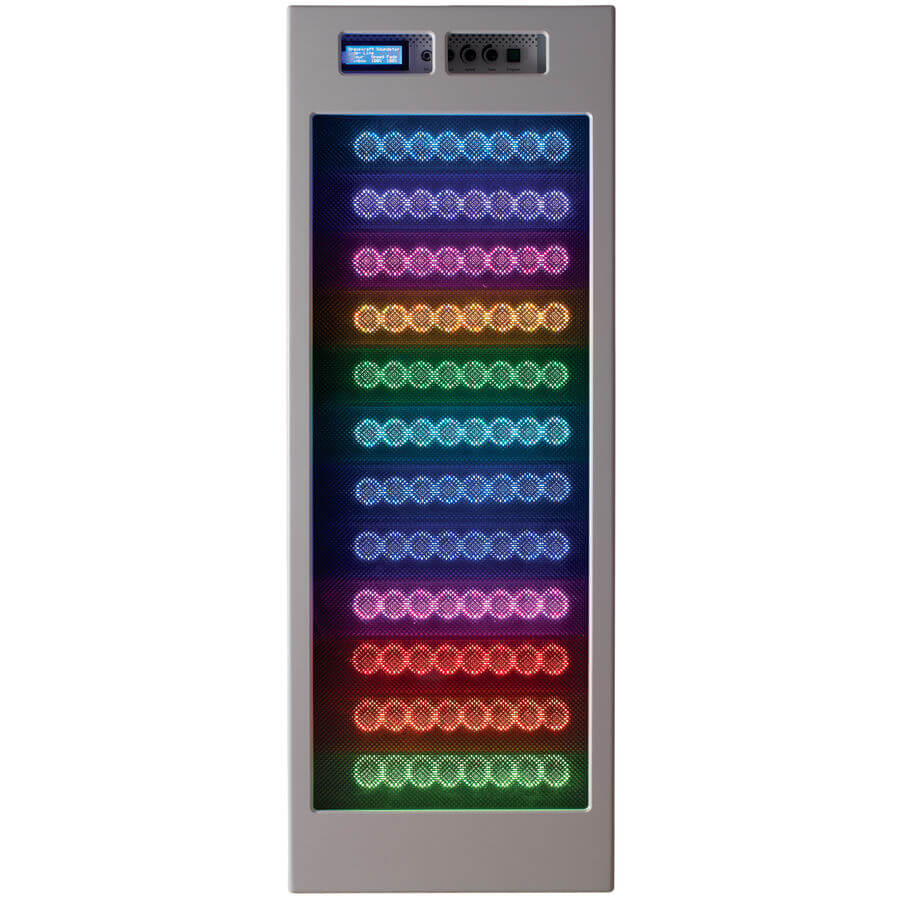
Fun and Function’s Sensory Steplite $2300 
Flaghouse’s Sound to Sight Showtime Panel $2600
What You Will Need
- Shadow Box Frame
- IKEA has a great line of cheap shadow boxes in the RIBBA series. Very affordable ($15?)
- I decided I wanted a nicer and sturdier frame, however. I also chose a frame company which could give me a high quality acrylic cover for the custom frame as well. Ours is 30″x20″ from Frame Destination which was about $150.
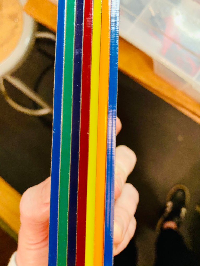
- Translucent Acrylic Panels from Delvie’s Plastics (or any plastics store)
- 20″L x 6″W x 1/8″ thickness
- 7 colored panels: Red, Orange, Yellow, Green, Blue, Violent, and White
- Each panel was about $8 and they cut them too!
- LED Lights
- Clear 3M Tape
- Duckbill Switch Panel
- This ranges depending on where you get your parts from. I got mine off eBay but here’s the exact replica from MGI Speedware.
- Strain Relief/Cord Grips
- DC 12v Male and Female 5.5mm Plug Adapters
- Shrink Tubing
- LED Connector Strips
- Tools:
- Soldering Iron
- Hole Saws
- Hand Drill or Drill Press
- Heat Gun
- Wire Cutters
- 3-in-one oil (always handy!)
- Total Estimate: $250 – $450
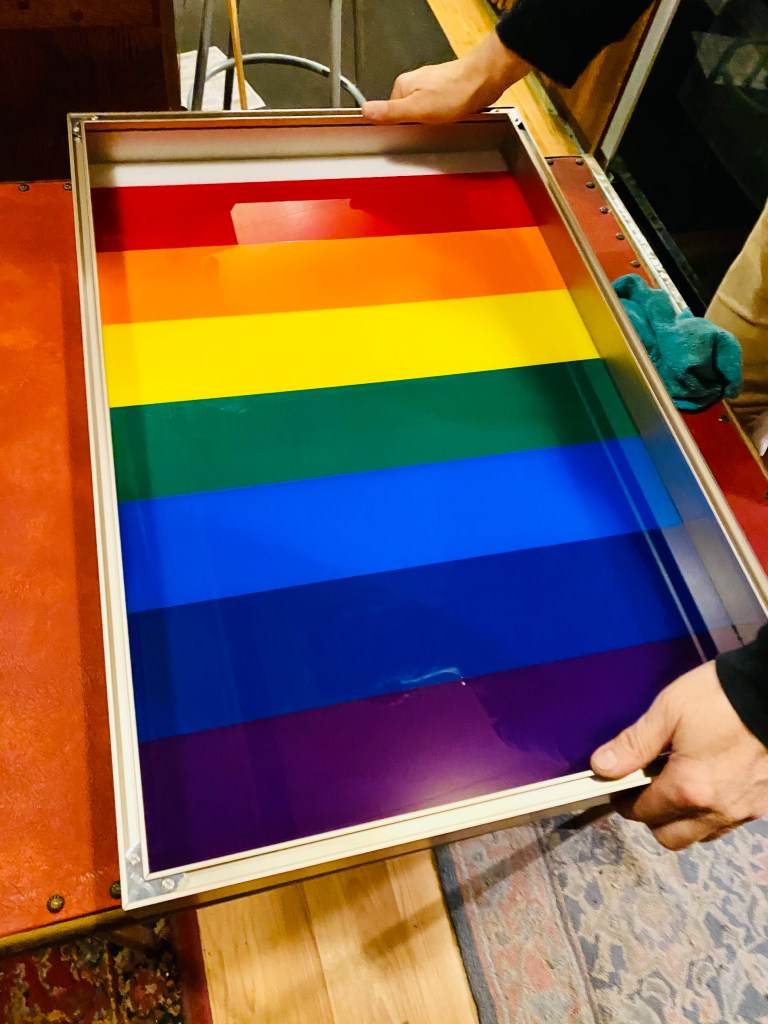
The Design
I think any color selection would look beautiful but I wanted a ROYGBIV pattern. I think that Montessori education has grilled that into me because apparently not everyone knows that acronym! But I basically wanted the colors of the rainbow in his sensory zen den. I also wanted the option for Tristan to independently turn on specific panels instead of having all of them on all the time (unless he wanted that option). This way it would allow him more independent use of the panel rather than turning on a switch. I also wanted to try to program into the panel a sound responsive light feature – which worked with a basic LED light strip!

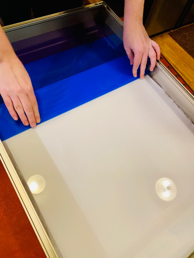
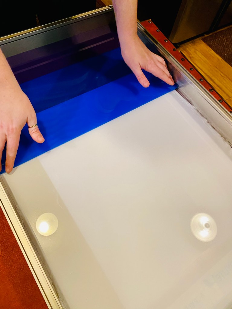
Part 1: The Acrylic Panels
First, we began by laying out the panels inside the shadow box frame. We laid some clear 3M tape down each side of the clear acrylic panel that came with the frame and put down each color accordingly. Be sure to clean each panel before it goes down!

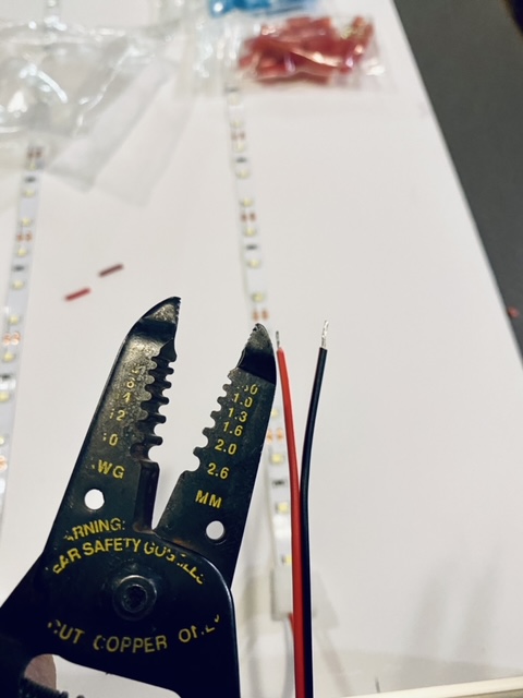
Part 2: White LED Lights
Part 2 involved laying down the white LED strips. I wanted them to go in the middle of each colored acrylic panel basically. So we measured the middle of each panel and its corresponding point inside the frame. Then put the LED strips down and cut them to size. Then we put on the LED connector strips. First peel back the sticky part of the LED strip to reveal a positive and negative connection points underneath. Be careful to only just make contact however as if you push the LED strip in too far to the connector, it won’t light up (as we found out!). Since knew we would be connecting these cut LED strips to the wires in the toggle switch panel, I used wire strippers to strip the coating off the LED connectors.


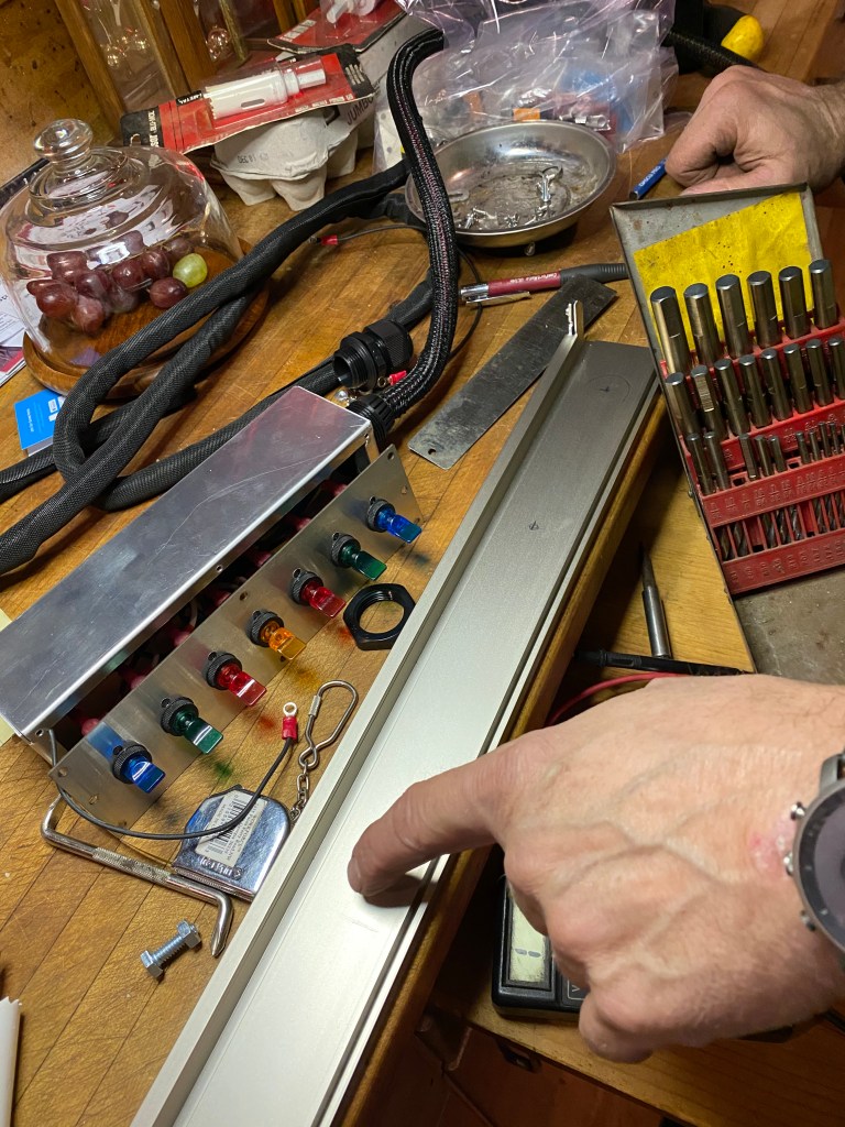
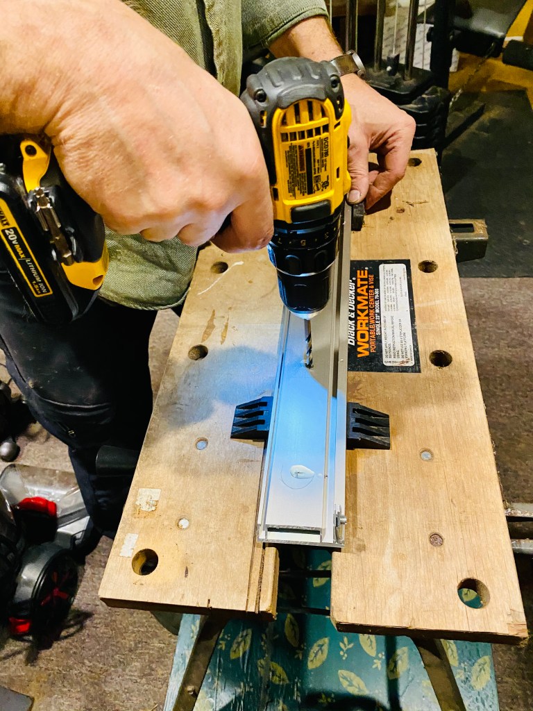
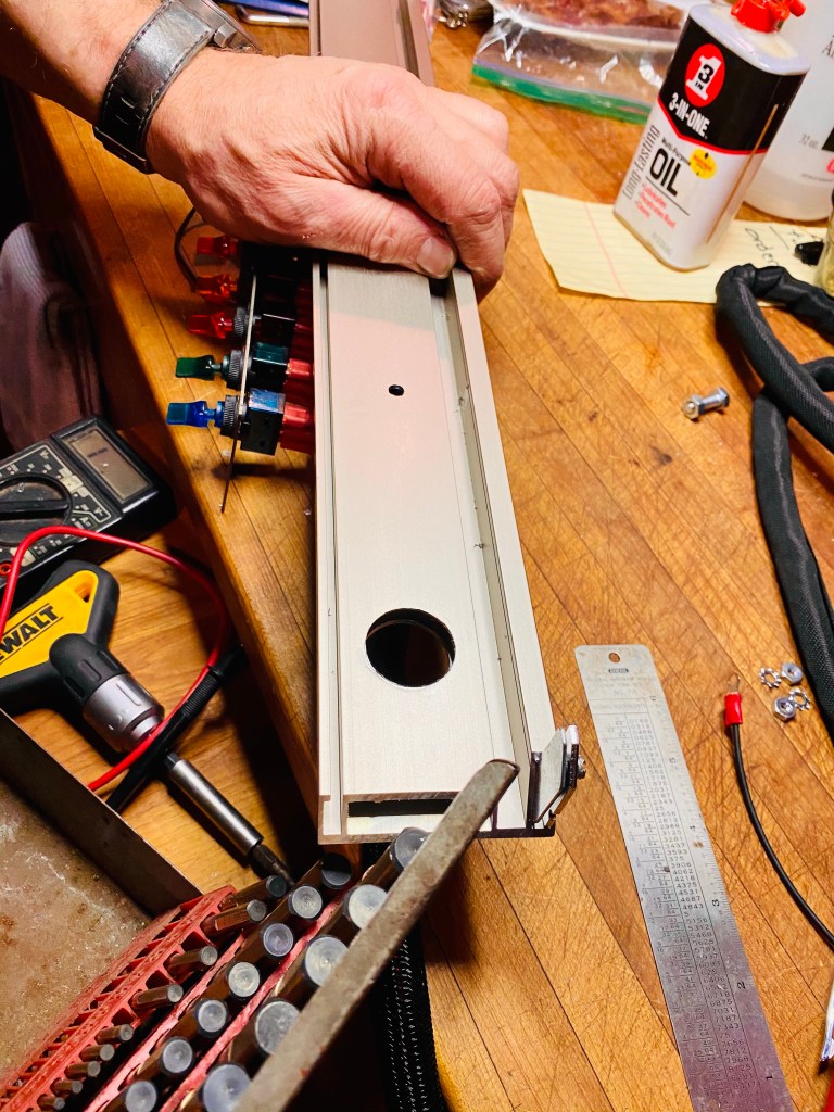
Part 3: Drilling and Attaching the Toggle Switches
Next we drilled a big enough main hole to put the wiring from the toggle switch panel into the frame. This way the electrical box that the switch panel was in would then be connected to the metal frame, thus making it all one unit and grounded. We also drilled another hole for the main power line to be plugged into the wall. We then added the grip cord or strain relief to the hole (this goes around the wires). Basically it is to prevent Tristan from potentially grabbing part of the panel and pulling out all the wiring.


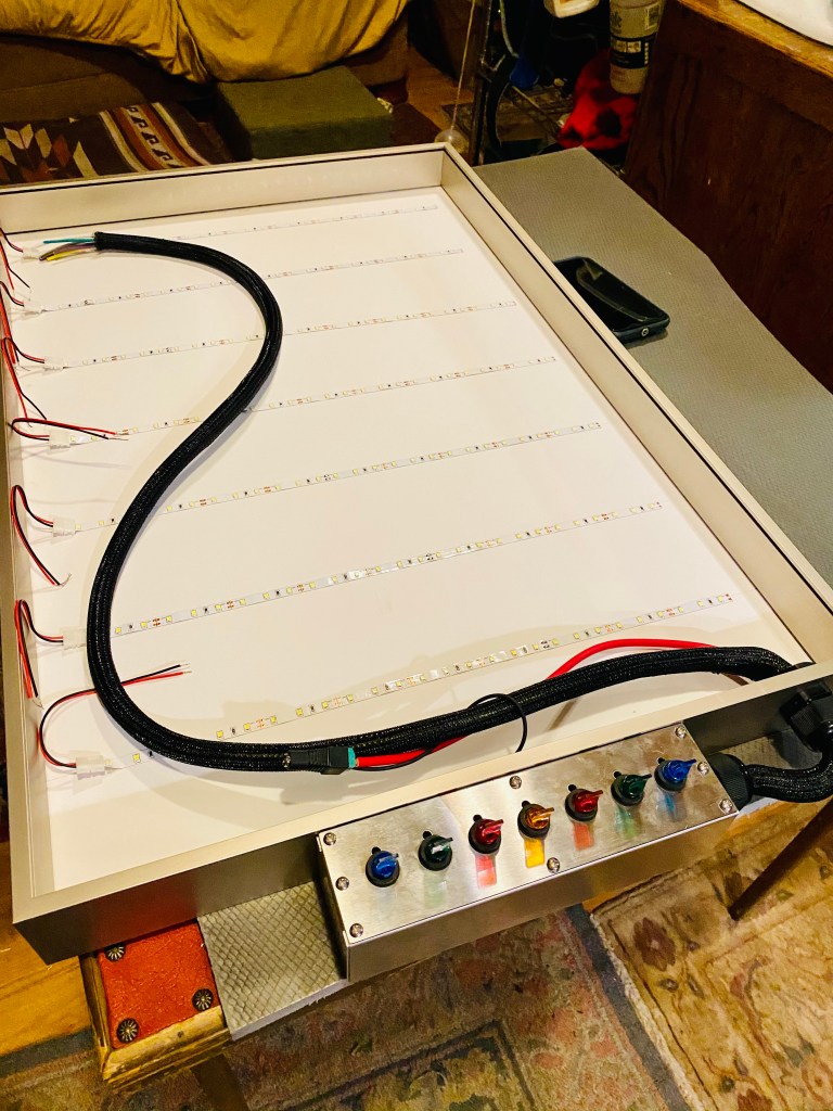
Part 4: Wiring and Connecting
This next part was a long process! It was several hours of wiring, soldering, and making sure the connections work. This was almost all done by Karl! I am definitely still learning this part of the engineering process but it’s starting to come to me (both the terminology as well as the process).
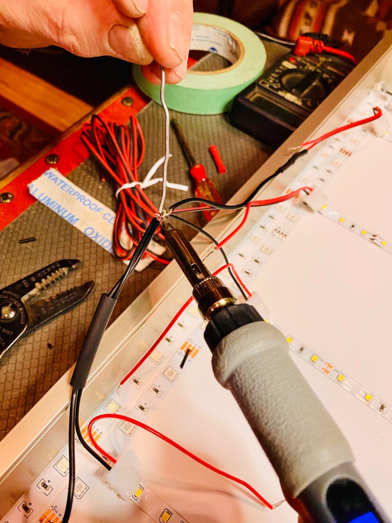
First he made sure all corresponding wires (each toggle has a corresponding wire) aligned with each colored panel wire (the white LED strips). Then each wire has to be tied together to the LED strip to make contact and then the soldering begins! The black wire is for grounding and the red wire is for powering basically. After soldering all corresponding wires together, shrink tubing and a heat gun was used to seal the connection basically so it doesn’t come apart and it gives the connection some extra support. During this time, we also ran the second LED sound activated strip around the inside of the frame twice. We left the microphone receiver on the outside of the frame and pulled the wiring through the strain relief. We then used a voltmeter to test the connectivity of each part of the project (wow, this was helpful as not all connections were working and we had to troubleshoot which ones were not working and why). Finally, after several hours of this, we moved on to wire management and just used some LED wire holds and some zip ties to help make it look a bit neater on the inside.


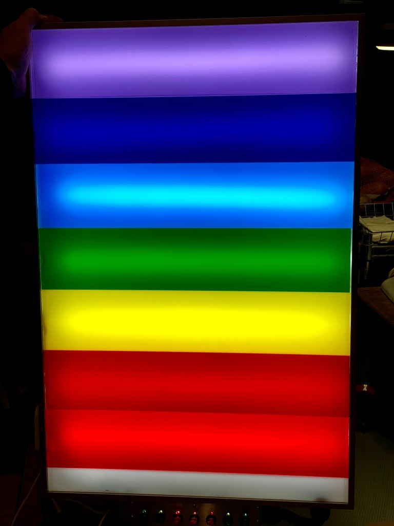
Part 5: The Reveal
Finally, the best part! We were able to see the Rainbow Light and Sound Panel in action!
